We live and breathe rotary valves, but we understand if they’re still a bit mysterious to you. What’s behind those shiny metal plates, what makes them spin, and how do they stay sealed? Whether you’re new to the dry bulk processing industry or just want to brush up on your knowledge, this guide will help you understand what makes valves tick.
Let’s start with terminology. Rotary valves are also called rotary feeders, rotary airlocks, or a combination of those terms (e.g., “rotary airlock valve”). Or just valves for short. The term you use might depend on the application, but they’re generally all correct.
These are the basic components of a rotary valve:
- Housing
- Rotor and shaft assembly
- Two endplates
- Seals and bearings
- Motor and drive assembly

A quick note on valve variations
Valves have plenty of variations, as you can see from a quick glance at our product page, because many are designed for specialized applications. For example, some have rotor assemblies built on a rail system, which allows for easier maintenance, while others have added manifolds that help aerate sticky materials. Even so, most rotary valves share these same basic components.
The valve’s ‘chassis’
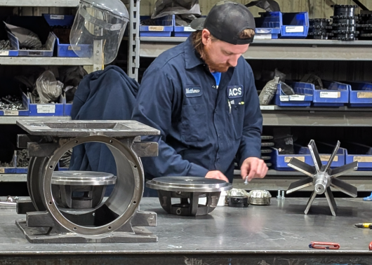
The housing is exactly as it sounds — it’s the sturdy shell that houses all the other components, sort of like the chassis of a car. The inside of the housing contains the rotor, while other parts like the bearings, seal, and endplates are affixed to the outside.
The ports on either side of the valve are called the inlet and outlet. Your dry bulk material is unloaded into the inlet (the top port), passes through the housing via the rotor, and is released through the outlet (the bottom port) into its next container.
Key pillars of valve construction
It’s important for a valve housing to have a smooth, solid construction. Any cracks or crevasses can create a risk of contamination and make the valve more difficult to maintain.
To that end, the valve's housing and endplate are usually made with a computer numerical control (CNC) machine. The CNC machine allows machinists to shape parts with a high degree of precision, ensuring a strong and crevasse-free construction.
A crucial part of valve design is to maintain very small and specific clearances between the rotor tips and valve housing, called rotor-to-housing clearances or tolerances. These need to be measured regularly to ensure strong performance and NFPA compliance.
Always on rotation
Now we get to the action: the valve’s rotation. That’s the rotor’s job.
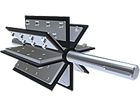
The rotor assembly is essentially a series of six or more vanes attached to a cylindrical shaft. Think of a paddle wheel or the water wheel on an old-fashioned mill. The vanes or blades are like the spokes of the wheel, and the pockets are the spaces between each vane. It’s a simple design but critical to the valve’s operation.
The shaft connects to a motor that powers its rotation. As the motor runs, the rotor turns, carrying material from the inlet to the outlet like a set of rotating pockets. This demonstration shows what it looks like from the inside: [show valve cross-section video]
As you can see, only about half of the rotor vanes are holding material at any given time, while those in the free half return up the other side to receive new material. That means while the rotor is always making a circular motion, the material itself is moving in a downward direction from top to bottom.
Going from inlet to outlet: the load side of rotation (vanes are carrying material).
Going from outlet to inlet: the return side of rotation (vanes are empty).
Keep it sealed
The valve’s inlet and outlet are always sealed against airflow, even as they receive material from one container and release it into the next. To maintain the seal, at least two rotor vanes must have close contact with the housing at all times, depending on how many vanes your rotor has (usually 6, 8, or 10). The more vanes you have, the better the seal.
If too much air enters the inside of a valve, it loses its essential function as an airlock. A compromised seal can cause material flow issues or leaks, because the unwanted air can block material from entering the pockets or even escape up the return side through the inlet. Put simply: that’s not good.
To work effectively, a rotary airlock should maintain a consistent pressure differential between the inlet and outlet. The best way to do this is to keep a regular maintenance schedule and ensure your valve is correctly sized and configured for your application.
Jump down the rotary rabbit hole
Want to keep up with your rotary valve studies? Here are some other helpful resources:
- Learn how to check your rotor-to-housing tolerances.
- Find out which shaft seals are best to reduce downtime.
- Get an overview of each type of valve coating.
- Understand why bearings are crucial to valve safety.
- See how direct-drive motors make maintenance and operation easier.
Get some expert guidance
We threw a lot of information at you about airlocks, housings, rotors, ports… It’s a lot, we know. The good news is you don’t have to know it all back-to-front — that’s why we’re here. Give ACS Valves a call and ask us any questions you have about the best rotary valve for your application.


