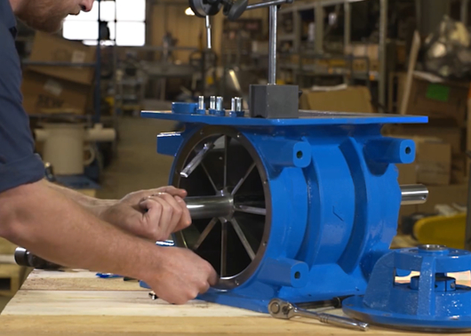
Checking rotor-to-housing tolerances is an essential part of owning a rotary airlock valve. To prevent material flow issues and keep your valve in compliance with NFPA regulations, tolerances (also called clearances) should stay within a range of 0.0079’’ or less.
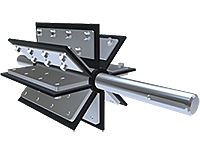
This should be part of your regular maintenance schedule! If your clearances get too large, material will be more prone to leaking through the airlock, which means reduced performance and loss of NFPA compliance. That’s when it’s time to replace the rotor.
Thankfully, it’s a straightforward process. We put together this guide to walk you through the steps.
Tools to use:
- Allen wrench (AKA hex key)
- Small flat punch
- Drift pin
- Dial indicator
- Gear puller (AKA wheel puller)
- Feeler gauges
First, how do you access the rotor?
If the inlet or outlet of your rotary valve is accessible, you can measure the rotor-to-housing clearances directly through one of these openings.
Otherwise, you will need to remove the endplate before performing your inspection. It’s easier to do this tail-side, because then you won’t need to remove the drive package. We have another how-to guide explaining the endplate removal steps.
How to check rotor-to-housing tolerances
Step 1: Remove the chain drive guard
If your valve has one equipped, loosen and remove the chain drive guard and disconnect the drive chain.
Step 2: For an accessible inlet or outlet, just measure
If neither the inlet nor outlet of your valve are accessible, skip ahead to Step 3. Otherwise, start by numbering each rotor blade to make them easier to remember as you check.
Then measure the gap between the rotor blade and housing at each end of the blade. Check the inlet and outlet by measuring the side clearances between the rotor blade and endplate.
And you’re done! Scroll down to see more NFPA resources or contact us if you need more help.
Step 3: Remove the bearing locking collars
Remove the Allen set screws from the locking collars on both sides. Peen down the groove formed by the set screws using a small flat punch.
Loosen the collar by rotating it in the same direction as the shaft rotation. Put a drift pin through the hole (not the threaded set screw hole) and tap it with a hammer to rotate the collar. Then just slide the collar off the shaft.
If your valve is equipped with an ACST-4 Shaft Seal, use a 1/4" Allen key (5/16" for larger valves) to loosen the lock collar clamping the teflon seal to the shaft (on both sides). On valves equipped with a "push-type" seal assembly, loosen the pusher nuts, allowing the pusher to retract from the Teflon packing.
Step 4: Measure the side-to-side clearances
To measure the clearance between the rotor and endplate, attach a dial indicator to the end of the shaft and set it to zero.
Push the shaft towards one endplate, and the indicator will show the side-to-side clearance measurement. There should be a minimum of 0.0079’’ on either side of the rotary valve.
Step 5: Remove the tail-side endplate
Next, you need to measure from the outside diameter of the rotor to the housing. Put the indicator away and take off all bolts from the tail-side endplate. Remove the endplate from the housing using a wheel puller tool.
Step 6: Use the feeler gauges
Lastly, take out your set of feeler gauges. Put the gauges between the housing and both the bottom and top rotor blades until you feel friction from both feeler gauges.
All done?
You should have two sets of measurements by the end of this process. If you need a visual guide, you can always review the steps in this video:
Here are a few more handy resources:
- A video guide to reassembling your valve
- What is an NFPA compliant valve?
- All the NFPA resources you need for valves in one place
For more technical support or to order replacement rotors for your valve, get in touch with an ACS Valves expert. We look forward to helping you out!


